A sliding gate can have the right rack-to-pinion clearance when it is closed and still bind halfway open. Check three things separately across the full travel: the clearance at the mesh, how much of the tooth face overlaps, and whether the tooth spacing stays consistent across each rack joint.
Say a newly installed driveway gate clicks once near the middle every time it opens. Mark the position of the gate and note the direction of travel. Then see which rack joint is passing the pinion, which wheel is crossing a track joint, and what is passing through the guides. A repeatable click tells you where to look. The sound alone doesn’t tell you which part is at fault.
Separate gate support from the drive
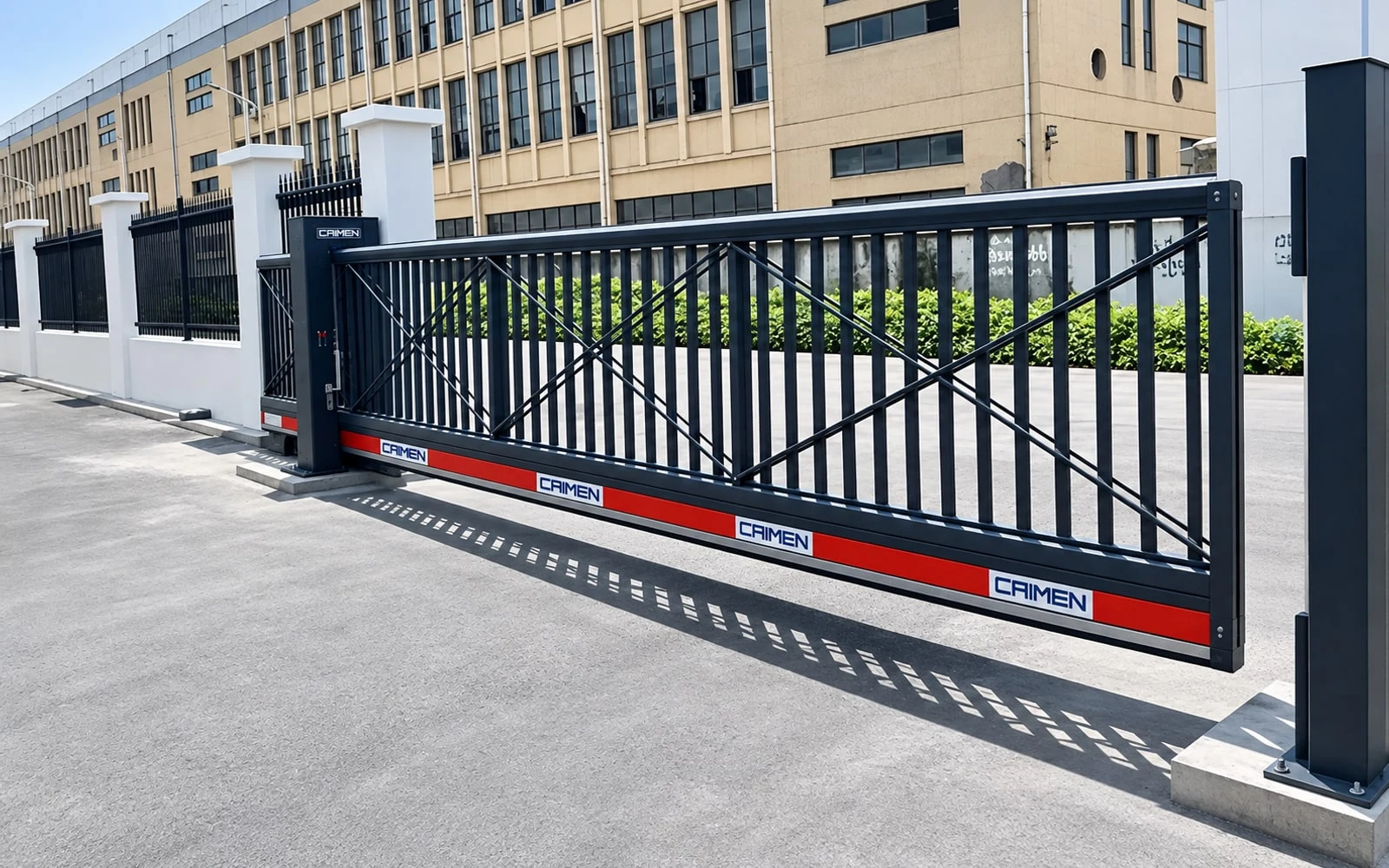
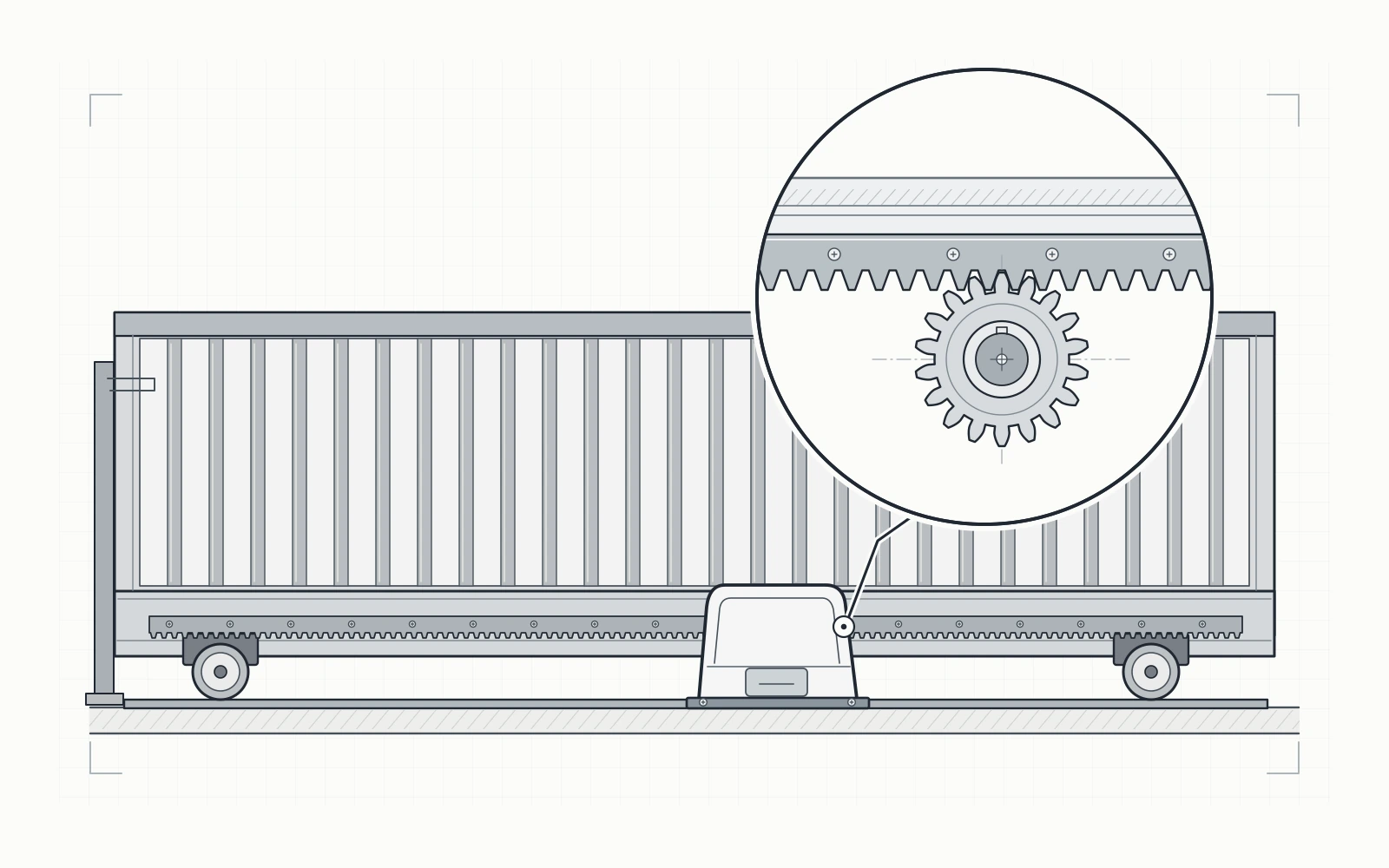
The drive pinion turns against a gear rack fixed to the moving gate. The rack transmits the drive force; the pinion should never carry the gate’s weight. A tracked gate rides on wheels and a ground track. A cantilever gate rides on the support assemblies specified for its beam. Check how the leaf is supported before adjusting the rack. Our visual guide to sliding gate parts shows how the supports, guides and drive fit together.
Before checking the drive, have the installer isolate the relevant power sources and secure the leaf against unintended movement according to the equipment instructions. Pause if the leaf cannot be safely controlled, could roll on its own, or has visibly damaged supports. Keep hands and tools clear of the rack, pinion and guides whenever the gate is moving.
If the gate still catches at the same point after the operator is released as the manufacturer allows, check the track, wheels, guides or supports. The manual release can free the drive without physically separating the pinion from the rack. Manual movement gives you a useful clue, but it may not isolate the gear mesh. Use the equipment maker’s procedure to confirm what you are actually testing.
Check clearance, tooth contact and rack joints separately
| Check | What to look for | What can be missed |
|---|---|---|
| Mesh clearance | Use the measurement point and method in the operator manual. Compare readings near closed, at mid-travel and near open. | A single reading at the closed end misses changes along the rack. Tooth-tip clearance and backlash describe different gaps; use the one shown in the manual. |
| Tooth-face overlap | Check how much of the rack and pinion tooth faces overlap across their width. Compare it with the manufacturer’s requirement. | The teeth can look aligned from the side while making contact at one edge. If overlap changes as the gate moves, check for sideways movement of the leaf or guides. |
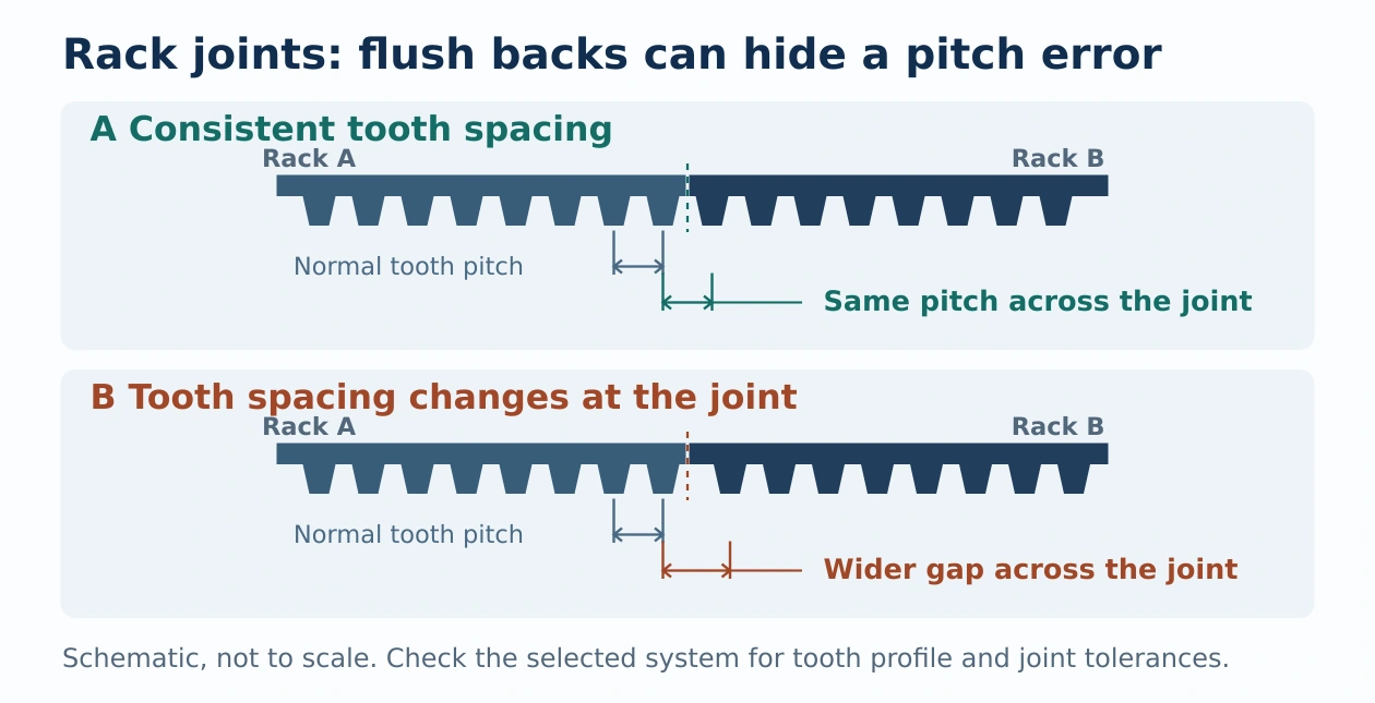
| Rack joints | Compare the spacing of the two teeth across each seam with the spacing between neighboring teeth. Check the joint for a step in height or a sideways offset. | The backs of two rack sections may sit flush while the pitch across the seam is wrong. Matching pitch also doesn’t prove the sections sit at the same height. |
Some manuals use the pinion to position the rack during assembly and call for a separate adjustment to set the final running clearance. Record the operator model, rack specification, manual page or figure, and final readings. Use the acceptance range for that combination.
Record checks from the closed end to the open end
Number the rack joints on the layout, for example J1 and J2. Record which section of the rack is passing the fixed pinion. A note such as “near J2, opening” is much easier to act on than “halfway.” Take readings with the leaf stationary and secured. Then have the installer verify opening and closing using the manufacturer’s procedure, observing from outside the travel path and pinch zones.
Use the positions below as a starting point, and add a line for each additional joint or suspect section. Near the ends of travel, use the manufacturer’s permitted inspection positions. Do not move the leaf past a limit or stop to take a reading.
Full-travel rack alignment checklist
| Inspection point | Mesh clearance / units | Tooth-face overlap | Rack joint condition | Correction / retest |
|---|---|---|---|---|
| Near fully closed | ||||
| Rack joint J1 | ||||
| Mid-travel, away from joints | ||||
| Rack joint J2 | ||||
| Near fully open |
Add a line for each additional joint. Use the selected operator manual for measurement points, methods and acceptance limits. This checklist covers mechanical alignment; record safety function tests separately.
For any irregularity, record the direction, the exact point or length affected, and what changed on the recheck. Repeat the required checks once the rack and operator are finally secured. A reading taken while hardware is still loose does not describe the finished installation.
If the gate still clicks at the same spot, what do you check next?
| What you observe | Where to look first | What to record |
|---|---|---|
| One short click as J2 passes the pinion | Check tooth spacing across J2, the step between sections, sideways offset and fasteners. If there is also a track joint nearby, check when the wheel crosses it. | Leaf position, direction of travel, and whether the click occurs as the pinion crosses the seam. |
| Noise over a stretch as clearance narrows | Check the leaf’s travel path, supports and guides first, then the rack mounting line and the operator base. Adjusting one rack section can hide a travel problem without fixing it. | Readings where the change starts, where it is greatest and where it ends, plus a reading from a quiet stretch for comparison. |
| Wear toward one edge of the teeth | Look at tooth-face overlap and whether the operator base is skewed relative to the gate. If the wear is confined to one stretch, check whether the leaf shifts sideways there. | Photographs of the stationary teeth and hardware, labeled with their location. Treat wear as a clue and verify it against measurements. |
| Noise only near fully open or fully closed | Along with the gear mesh, check the limit triggers, mechanical stops and receiver against the equipment drawings. | Whether the noise starts before slowdown, when the limit triggers, or as the leaf meets the receiver. |
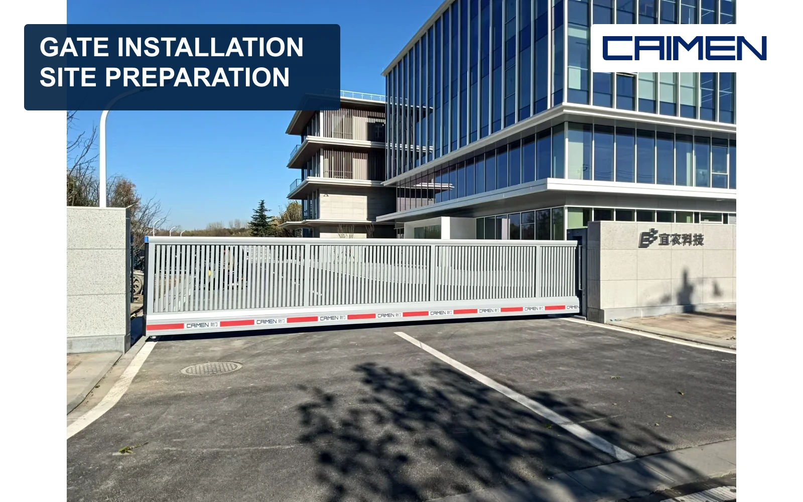
If the operator base has shifted, or the symptom first appeared after an anchor or baseplate adjustment, check the drive position and the gate’s travel path together. Our cantilever gate site preparation guide covers the support layout and installation documents to have on hand. If the gate mainly reverses or stops short while closing, see our guide to an automatic gate that won’t close to help distinguish a control or safety input from mechanical interference.
Frequently asked questions
What gap should there be between a sliding gate rack and pinion?
Use the value and measurement method specified for the selected operator and rack. Record where you measured, how you measured and the permitted range. A clearance quoted for another model is not an acceptance value for your installation.
Is it enough to butt the ends of two rack sections together?
No. Rack ends and joining methods vary. Across each seam, check tooth spacing, the height of both sections and their side-to-side alignment. Recheck the joint after tightening the fasteners.
Can you mix nylon and steel rack sections?
Only if the operator and rack suppliers confirm that the combination is compatible. Check tooth profile, module, mounting method and load rating. When replacing a section, check that the pinion meshes correctly across the transition to the existing rack.
Will raising the operator force fix occasional binding?
Increasing the force will not correct a misaligned joint, interference between teeth or a gate that runs out of line. Have the installer find and correct the mechanical issue, then verify drive operation and protective functions as the manufacturer requires.
Is one successful pass enough to sign off the installation?
One clean pass doesn’t show how every joint behaves in both directions or confirm the safety functions. Record the mechanical checks, powered operation and protective device tests separately. Note the results of any retest after corrective work.