Cantilever sliding gate calculations need a defined gate arrangement: its opening, complete moving leaf, weight, support system and site conditions. Opening width alone cannot establish the required beam, carriage spacing or foundation. A useful calculation starts by making those inputs clear, including what each dimension and weight actually represents.
A hardware selector can help identify a compatible component arrangement within its stated limits. It does not, by itself, establish that the gate frame, supporting works and powered entrance are suitable as a complete system.
Define the length and weight being entered
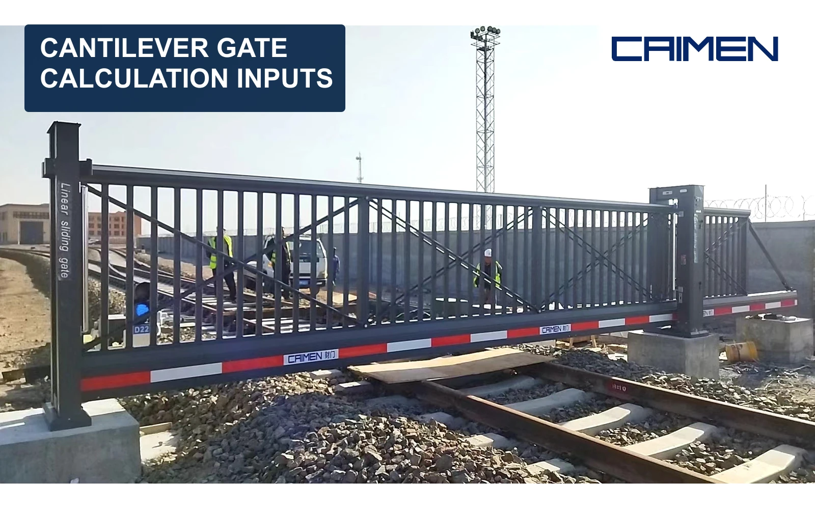
The clear opening, overall leaf length and spacing between supports are different dimensions. The leaf includes the section that closes the entrance and the rear extension. That rear section belongs to the moving assembly even when it remains behind the boundary. The cantilever support principle explains how the leaf is carried beside the driveway.
Weight needs an equally clear definition. Some hardware selection tools ask for the estimated weight of the opening portion before proposing an overall arrangement. A calculation for the completed moving assembly needs to identify the parts included in its own weight input. Those two entries are not interchangeable without checking the method.
List the frame, infill, running beam and attached moving equipment within the relevant scope. Record whether the figure is an estimate or a confirmed assembly weight. Changing an open-bar infill to a solid panel changes the input; retaining the earlier weight would leave the calculation describing a different gate.
Treat the frame and running hardware as one arrangement
The gate frame must support its own span without relying on the running hardware to correct an unsuitable frame. A carriage provides the rolling support; the beam is the moving member that runs through or over the selected support arrangement. Their compatibility and positions matter together.
For our cantilever sliding gates, the running beam works with fixed roller carriages beside the entrance. We configure support positions, foundation requirements and side runback around the gate and site. A component rating is therefore not a stand-alone rating for every complete gate built around it.
Counterbalance length and carriage spacing belong to the selected system configuration. A familiar rear-section percentage is not a substitute for that configuration. Before using a selection result, check which hardware model, beam and gate geometry it assumes.
Keep site loads and foundations in the calculation scope
Gate weight is only part of the supporting arrangement’s duty. Wind acts on the leaf, and the gate’s movement introduces dynamic effects. Height, infill and exposure therefore need to remain visible in the design information. A solid screen and an open-bar leaf cannot be treated as equivalent simply because they close the same width.
Foundations and mountings transfer the gate’s actions into the supporting ground. Their design depends on the actual arrangement and site conditions. A generic concrete block size cannot establish suitability at a different site. Ground information and any existing supporting works need their own assessment.
The cantilever gate site checklist covers the observations needed to describe opening space, runback and ground levels. Those observations supply context for the design; they are not structural calculation results.
Make the inputs traceable
| Input | What the record needs to distinguish |
|---|---|
| Geometry | Clear opening, overall leaf, height and support positions |
| Weight | Opening portion or complete assembly; included parts; estimate or confirmed value |
| Running system | Selected beam and carriage model, arrangement and applicable limits |
| Site loading | Infill, exposure and the design conditions being assessed |
| Supporting works | Foundation arrangement, ground information and existing structures |
| Operation | Intended use and movement conditions for the selected equipment |
A useful calculation record identifies the drawing revision, hardware configuration, input sources and assumptions. If an input is unknown, leave it identified as unknown rather than substituting an attractive value from a different gate. When the design changes, the record should show which inputs need checking again.
Structural selection also has a clear boundary. It does not settle powered-gate hazards, protective equipment or commissioning. Those depend on the complete entrance and how it will be used. Keeping these responsibilities distinct makes a calculation useful without giving it a wider meaning than it can support.